
Setting VRM Template in Unity
Setting Anthro Canine Template

In the previous tutorial we learned how to configure and export a VRM model from Blender, now we will do the same from Unity. Although it is possible to create a complete VRM model using Blender, without the need for other software, configuring it using Unity has its advantages, as I will exemplify in this tutorial, you will understand why. Remembering that this is from my point of view, there is no problem thinking otherwise.
We also deal with VRM 0.x and 1.0, in this case we will only deal with 0.x. I intend to make a tutorial dedicated to VRM 1.0 in the future, as so far, I have done few tests with models of this type.
The Blender VRM addon I used in past tutorials was version 2.20.12 and UniVRM was version v0.111.0 in this tutorial and others. If you use an updated version of any of these, some settings and features may be different on your system compared to those presented in this tutorial, please take this into account.
VRM Settings in Unity
Initially, it is not possible to create a 3D character from scratch in Unity, so you will need to create one in another software such as Blender and export it in a compatible format, such as FBX, and then import the model into Unity.
The flow of creating a VRM model is normally to import an FBX model (that follows some specifications) into Unity, configure it and export it as a Prefab VRM, using UniVRM, then configure it once again and export it as a VRM file. In fact, it is a time-consuming process, not to mention when it is necessary to update the model, whether due to changes in the mesh, such as Blend Shapes, influence weights, topology, UV Map, etc., or changes in the Armature (skeleton), such as changes in the properties of some bones.
As you, dear reader, may know that there is the VRM Add-on for Blender, which we used a lot in past tutorials. As we know, with it we can create a VRM model directly from Blender and then import and edit it in Unity, this way we don't have to deal with the FBX format, which allows us to skip several steps.
To continue with this tutorial you can use a VRM file from my samples (download link) or one that you exported yourself, if you followed the previous tutorial, Setting VRM Template in Blender. If you don't have Unity installed or don't have a project configured with UniVRM, read Quick VRM Edit in Unity for more details.
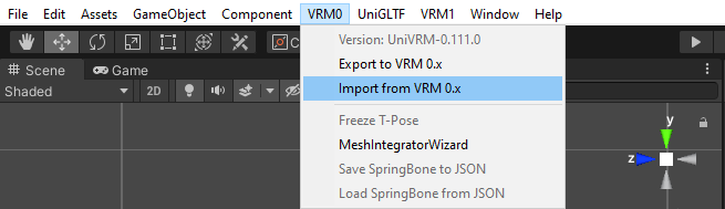
In my case, I'm going to use one of my samples. You can simply drag and drop a VRM file into a project folder and a Prefab and other files will automatically be generated, or go to Topbar, VRM0 > ‘Import from VRM 0.x’. The difference is that in the first the names of the generated files are relative to the name of the imported file, in the second we can choose the name of the Prefab VRM before importing and consequently the generated files will have names relative to the chosen name.
VRM Spring Bones and Colliders
With the model loaded into the scene we will notice that the Spring Bones are in yellow and the Bone Colliders are in magenta. This model is already configured, but I will remove some configurations to provide a better example.

If the Spring Bones and Colliders are not visible when the model is selected, go to Gizmos and enable ‘VRMSpringBone’ and ‘VRMSpringBoneColliderGroup’.

When the model is changed within a scene, the changes are applied only to the model in that scene. If the model is loaded in other scenes, these changes will not be present, because we only changed one instance of the model. For the changes to be definitive, we must change the model's Prefab. With the model selected, click on ‘Open Prefab’.

By default ‘Auto Save’ is already enabled, I prefer to leave it disabled and save the changes manually by clicking on ‘Save’, but this is at your own discretion. First let's check secondary, this GameObject is used to store the Spring Bones settings and is automatically generated when a VRM model is imported into Unity, so there is no need to worry about creating it in Blender or another 3D program.

In this model we have 4 components ‘VRM Spring Bone (Script)’, ‘Tai’l, ‘Ears’, ‘Fur Head Aside’ (facial hair) and ‘Breasts’. I will remove all except ‘Tail’. If the model does not have any of these components in secondary, go to ‘Inspector’, click on ‘Add Component’ and select ‘VRM Spring Bone’, set the ‘Comment’ property to ‘Tail’.

Below ‘Comment’, we have ‘Gizmo Color’, which is the preview color of the selected Spring Bone(s). Each group of Spring Bones can have its own color, which can be interesting to differentiate them if necessary.

Further down we have in ‘Settings’, we have:
Stiffness: influences how much the bone stays in place when the body is in movement. The minimum value makes the bone stay still in its original position, giving the influenced mesh a sagging appearance, while high values make the bone follow the rest of the body more, giving the influenced mesh a firm appearance.
Gravity Power: defines how much the bone moves towards gravity. With a value of zero the bone will not be affected by gravity, with higher values the bone is pulled by gravity.
Gravity Direction: Sets the gravity direction of the gravity force. If (Y = 1) => 'up', (Y = -1) => 'down', (X = -1) => 'right', (X = 1) => 'left' , (Z = -1) => 'backward', (Z = 1) => 'forward'. The vector axes are relative to ‘World Space’.
By default, Y = -1 to simulate the natural effect of gravity. It is possible to configure directions in X, Y and Z simultaneously, in practice, this could create a floating effect, which would be interesting for characters of supernatural origin, such as ghosts, for example.
Drag Force: influences how much the bone shakes when the body is in motion. The minimum value makes the bone swing a lot and higher values make it swing less.
Center: defines a reference point on the model, usually the ‘Root’ bone. By default, Spring Bones use the World Space origin to calculate their movements, but we can define a bone as a reference point and this new point will follow the model when it moves. In practice, 'Center' prevents the Spring Bones from swaying excessively when the model moves, whether walking or running, for example. The criteria for choosing the bone in 'Center' is to be at the top of the Armature hierarchy and cannot be closely related to any Spring Bone.
Root Bones: defines the bones that will be affected by the settings mentioned above. When selecting a 'parent bone' the 'children' will inherit its settings.
Hit Radius: this parameter is used to detect bone collisions with Colliders, the greater the radius value, the greater the detection range.
Collider Groups: defines the group(s) of Colliders that will be used by Spring Bone, more details later.
When the Spring Bone is configured, it is visible in the model as connected nodes, these nodes are the ‘Hit Radius’. Let's set 'Gravity Power' to 1.0 and 'Hit Radius' to 0.04 to make Spring Bone's effects more visible.

‘Collider Groups’ is empty, change its parameter (Array Size) from 0 to 3 and then new ‘Elements’ will be generated. In these elements we will link ‘VRM Spring Bone Collider Group’(s). In ‘Tails’ we will insert ‘Spine’, ‘UpperLeg-R’ and ‘UpperLeg-L’.

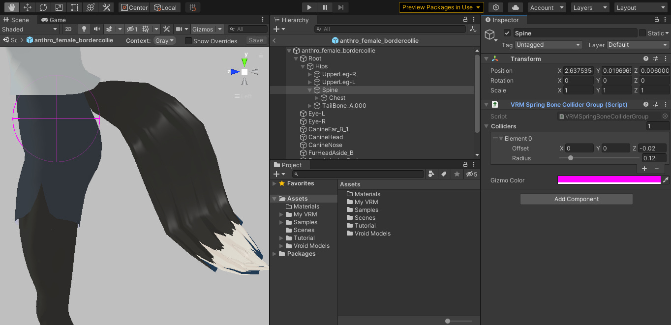
Assuming these bones are not configured, let's go to Root and look inside the hierarchy. Select ‘Spine’ and in ‘Inspector’ click on ‘Add Component’ and select ‘VRM Spring Bone Collider Group’.

Set the parameters of the Image below in the ‘Spine’ collider settings. Notice in the image that a magenta colored sphere was added and positioned in relation to the bone, this sphere is the collider itself.
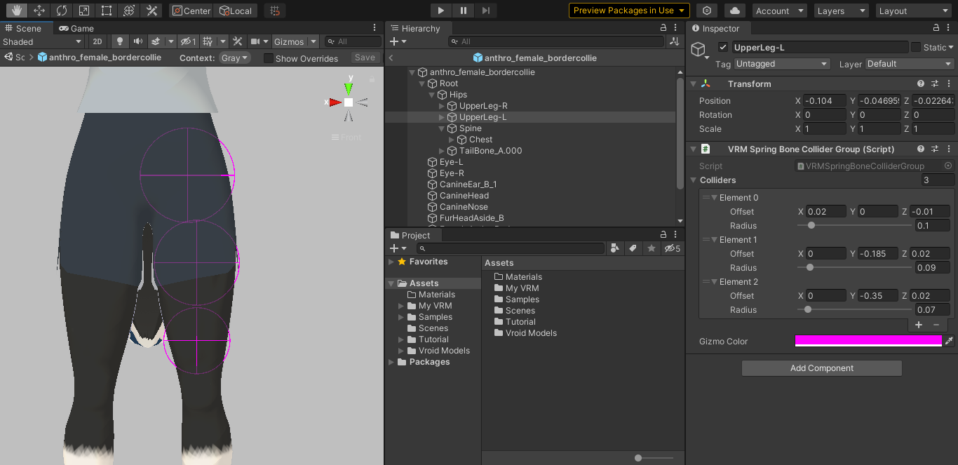
Now in UpperLeg-L (or UpperLeg-R), do similar, but with the values in the image below. Note that this time we created three colliders with the purpose of covering the entire upper leg area (more or less above the knee to one of the buttocks), as the body parts can have a varied and complex shape, it is unlikely that the colliders will fit perfectly, so we are left with an approximation that best fits.
Before configuring the UpperLeg-R (or UpperLeg-L) and repeating the same steps, we can do the following, still in the already configured leg, select the component '...Collider Group' and in the extra options (three dots) select ‘CopyComponent’.

With the other leg selected, in the first component (Transform), click on the extra options and select ‘Paste Component As New’, this will generate a new component with the same specifications but now relative to the current bone.

After the new component has been added, you may have noticed that the position of the first Collider does not look correct, this is because the X-axis position values of each bone are in the opposite direction relative to each other and the first of the colliders is in a non-zero position in X, remembering that the initial position of each collider is relative to its bone (Offset).

To solve this we can simply change the signal (direction) from X = 0.2 to X = -0.2, or go to the extra component options and select 'X Mirror', this will automatically make all colliders have their position mirrored in X. If many colliders were in non-zero positions on the X axis, 'X mirror' would be the preferable option.

If we changed the settings on one of the legs with new values and wanted to update the values on the other, we could use 'Copy Component' on the first and use 'Paste Component Values' on the second.
In the case of the upper legs, some 'VRM Spring Bone Collider Group' settings are simple and could be configured manually without needing too much trickery like 'Copy…' and 'Paste…', but imagine if we did the same in one of the arms, starting from the fingertips, going to the hand, lower arm, upper arm to the shoulder and then repeating the same steps on the opposite arm, it would be quite time consuming manually, in addition to the possibility of changing values and having to use them on the opposite side, but with the tricks explained in upper leg, component configurations become much easier.
With the ‘Spine’ colliders and both upper legs ready, let’s add them to the ‘Tail’ spring bone in ‘Colliders Groups’. Note that when trying to add a collider group, only bones with that component will be listed.

Now let's do some tests with the model in the scene. In the image on the left we see the model in the scene in 'Normal Mode' and on the right in 'Play Mode', as you can see the tail moves downwards with its 'weight' determined by 'Gravity Power'.


If you try to move the model in ‘Play Mode’ by selecting it directly, no spring bones effects will be visible. To do this we have to select the model from one of the bones. The selected bone cannot be the one defined in the 'Center' parameter in a 'Spring Bone' component, as this serves as a reference point, normally 'Root' assumes this role.

Still in 'Play Mode', we will change the rotation of 'Hips' to X = 90, then we will use the 'Rotate Tool' (in ToolBar) and rotate from one side to another, you can notice the tail colliding with the legs, if the colliders were not configured in the spring bone, the tail when swinging would pass through the legs without any collision, you can remove the colliders from the spring bone configurations and see how this happens in practice. Still with the colliders configured, you can also change the values of 'Radius' in the colliders and 'Hit Radius' in the spring bone to see how the collisions can vary. All changes made in 'Play Mode' are temporary and are reset when exiting this mode, which makes it a good environment for testing.
The big advantage of configuring colliders and spring bones in Unity is that they are configurable only through components. We cannot manipulate them as GameObjects in the scene, this prevents us from manipulating them accidentally, in addition to not adding many objects to the scene because components are like properties in each object.
In Blender, when we create a collider, it is added as a new empty object, which is selectable, which means we have to organize it in a collection together with other colliders to disable selection or visibility at certain times, when we have to manipulate other objects for example, in addition to making the scene more organized. We cannot copy and paste in the same way as we did in Unity, generally speaking, most of these configurations are done manually.
When we configure spring bones in Blender there are other limitations, such as the 'Hit Radius' which is not visible graphically, which makes it difficult to predict collisions. The worst part is that spring bone physics animations are limited to VRM 1.0 settings, making it difficult when we are creating a VRM 0.x model. This may change in future updates.
The icing on the cake is the possibility of saving and loading all VRM configurations of spring bones and colliders in an external JSON file. As these configurations can be time-consuming to implement, this file can serve as a backup when, for example, for some reason we need to re-import the entire model and overwrite the current one, if the armature is the same or similar, we will be able to load all the settings ready, perhaps with a few more adjustments if the armature is not so similar, still a great saving of time. Another possibility is to load these configurations into another model, without the need to repeat the model's steps with the ready-made configurations, as long as the armature is also similar.

Let's load a JSON file with spring bones configurations. In my Blender templates there are files of this type attached that can be found in the Workspace (tab) ‘Scripting’. You can extract them from there (for more details read Packed Data — Blender Manual) or simply copy and paste their contents and paste into an external .json file. It is good practice to save these files with the model name in front, something like ‘ModelName.Avatar_VRMSpring.json’. If you are having difficulty viewing or finding these JSON scripts in the templates, simply copy and paste the following scripts:
Male model:
{"boneGroups":[{"comment":"Tail","stiffiness":2,"gravityPower":0.5,"gravityDir":{"x":0,"y":-1,"z":0},"dragForce":0.4,"center":0,"hitRadius":0.04,"bones":[79],"colliderGroups":[2,1,0]},{"comment":"Ears","stiffiness":4,"gravityPower":0,"gravityDir":{"x":0,"y":-1,"z":0},"dragForce":1,"center":0,"hitRadius":0.02,"bones":[55,58],"colliderGroups":[9,10,14,12,11,13,3,4,8,6,5,7,15]},{"comment":"Fur Head Aside","stiffiness":2,"gravityPower":0,"gravityDir":{"x":0,"y":-1,"z":0},"dragForce":0.4,"center":0,"hitRadius":0.02,"bones":[61,64,67,70,73,76],"colliderGroups":[9,10,14,12,11,13,3,4,8,6,5,7,15]}],"colliderGroups":[{"node":2,"colliders":[{"offset":{"x":-0.025,"y":0,"z":-0.015},"radius":0.1},{"offset":{"x":-0.015,"y":-0.185,"z":0},"radius":0.09},{"offset":{"x":0,"y":-0.35,"z":0},"radius":0.07}]},{"node":6,"colliders":[{"offset":{"x":0.025,"y":0,"z":-0.015},"radius":0.1},{"offset":{"x":0.015,"y":-0.185,"z":0},"radius":0.09},{"offset":{"x":0,"y":-0.35,"z":0},"radius":0.07}]},{"node":10,"colliders":[{"offset":{"x":0,"y":0,"z":-0.02},"radius":0.135}]},{"node":16,"colliders":[{"offset":{"x":0.06,"y":0,"z":0.005},"radius":0.05}]},{"node":19,"colliders":[{"offset":{"x":0.01,"y":-0.005,"z":0.01},"radius":0.015}]},{"node":22,"colliders":[{"offset":{"x":0.015,"y":0,"z":0.0015},"radius":0.0125}]},{"node":25,"colliders":[{"offset":{"x":0.0225,"y":0,"z":0.0015},"radius":0.0125}]},{"node":28,"colliders":[{"offset":{"x":0.0125,"y":0,"z":0.0015},"radius":0.01}]},{"node":31,"colliders":[{"offset":{"x":0.0215,"y":0,"z":0.0015},"radius":0.0125}]},{"node":35,"colliders":[{"offset":{"x":-0.06,"y":0,"z":0.005},"radius":0.05}]},{"node":38,"colliders":[{"offset":{"x":-0.01,"y":-0.005,"z":0.01},"radius":0.015}]},{"node":41,"colliders":[{"offset":{"x":-0.015,"y":0,"z":0.0015},"radius":0.0125}]},{"node":44,"colliders":[{"offset":{"x":-0.0225,"y":0,"z":0.0015},"radius":0.0125}]},{"node":47,"colliders":[{"offset":{"x":-0.0125,"y":0,"z":0.0015},"radius":0.01}]},{"node":50,"colliders":[{"offset":{"x":-0.0215,"y":0,"z":0.0015},"radius":0.0125}]},{"node":52,"colliders":[{"offset":{"x":0,"y":0.115,"z":0},"radius":0.1}]}]}Female model:
{"boneGroups":[{"comment":"Tail","stiffiness":2,"gravityPower":0.5,"gravityDir":{"x":0,"y":-1,"z":0},"dragForce":0.4,"center":0,"hitRadius":0.04,"bones":[83],"colliderGroups":[2,1,0]},{"comment":"Ears","stiffiness":4,"gravityPower":0,"gravityDir":{"x":0,"y":-1,"z":0},"dragForce":1,"center":0,"hitRadius":0.02,"bones":[55,58],"colliderGroups":[9,10,14,12,11,13,3,4,8,6,5,7,15]},{"comment":"Fur Head Aside","stiffiness":2,"gravityPower":0,"gravityDir":{"x":0,"y":-1,"z":0},"dragForce":0.4,"center":0,"hitRadius":0.02,"bones":[61,64,67,70,73,76],"colliderGroups":[9,10,14,12,11,13,3,4,8,6,5,7,15]},{"comment":"Breasts","stiffiness":4,"gravityPower":0,"gravityDir":{"x":0,"y":-1,"z":0},"dragForce":1,"center":0,"hitRadius":0.02,"bones":[79,81],"colliderGroups":[9,10,14,12,11,13,3,4,8,6,5,7]}],"colliderGroups":[{"node":2,"colliders":[{"offset":{"x":-0.02,"y":0,"z":-0.01},"radius":0.1},{"offset":{"x":0,"y":-0.185,"z":0.02},"radius":0.09},{"offset":{"x":0,"y":-0.35,"z":0.02},"radius":0.07}]},{"node":6,"colliders":[{"offset":{"x":0.02,"y":0,"z":-0.01},"radius":0.1},{"offset":{"x":0,"y":-0.185,"z":0.02},"radius":0.09},{"offset":{"x":0,"y":-0.35,"z":0.02},"radius":0.07}]},{"node":10,"colliders":[{"offset":{"x":0,"y":0,"z":-0.02},"radius":0.12}]},{"node":16,"colliders":[{"offset":{"x":0.06,"y":0,"z":0.005},"radius":0.045}]},{"node":19,"colliders":[{"offset":{"x":0.012,"y":-0.0025,"z":0.006},"radius":0.0125}]},{"node":22,"colliders":[{"offset":{"x":0.015,"y":0,"z":0.001},"radius":0.01}]},{"node":25,"colliders":[{"offset":{"x":0.02,"y":0,"z":0.001},"radius":0.01}]},{"node":28,"colliders":[{"offset":{"x":0.01,"y":0,"z":0.001},"radius":0.008}]},{"node":31,"colliders":[{"offset":{"x":0.02,"y":0,"z":0.001},"radius":0.01}]},{"node":35,"colliders":[{"offset":{"x":-0.06,"y":0,"z":0.005},"radius":0.045}]},{"node":38,"colliders":[{"offset":{"x":-0.012,"y":-0.0025,"z":0.006},"radius":0.0125}]},{"node":41,"colliders":[{"offset":{"x":-0.015,"y":0,"z":0.001},"radius":0.01}]},{"node":44,"colliders":[{"offset":{"x":-0.02,"y":0,"z":0.001},"radius":0.01}]},{"node":47,"colliders":[{"offset":{"x":-0.01,"y":0,"z":0.001},"radius":0.008}]},{"node":50,"colliders":[{"offset":{"x":-0.02,"y":0,"z":0.001},"radius":0.01}]},{"node":52,"colliders":[{"offset":{"x":0,"y":0.115,"z":0},"radius":0.0925}]}]}Now with the settings loaded, test in ‘Play Mode’, change values if necessary.
A detail to be observed is the distribution of the colliders in relation to the spring bones, for example, the colliders related to 'Tail' correspond to the entire region of the hips and upper legs, this is because the probability of the tail colliding with this region of the body is bigger. We could configure hand colliders to collide with the tail, but as it is difficult to reproduce the movement of touching the tail itself in MOCAP applications that only use the camera (I currently do not have VR devices), I decided not to include the hands in the collision with the tail. . The hands make collisions with the ears, facial hair and breasts (only in the female model), although a little far from these regions of the body, it is easy to reproduce these collisions in MOCAP applications, since most of them are more focused on the body higher. Another detail is that the sample models do not have colliders on the chest and along the entire length of the arms to the shoulders, this is because there are no spring bones with the reach to reach them, such as long hair or long hair on the neck or torso.


If you have any doubts when creating spring bones and colliders, you can create some models in VRoid Studio, export them in VRM format, import them into Unity and use them as a reference. Create examples with different types of clothes and hair, observe the structure of their armatures and how the colliders and spring bones are distributed.
VRM model file structure
Now that we've demystified spring bones and colliders, let's take a look at the file structure of our model in assets.

Avatar: contains a file with all armature data. It is not editable and its content cannot be viewed in Unity, but in an external application such as NotePad++, I recommend not trying to edit it.

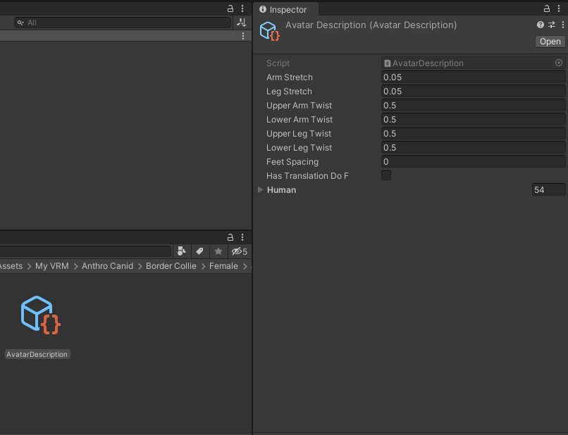
Avatar Description: contains settings similar to Avatar Muscle & Settings, but specifically to 'Additional Settings'. The Stretch Setting determines how much the joints can stretch when the limbs reach their maximum extension. Twist Settings determine how much the twist of one joint affects its neighbors. Feet Spacing determines the spacing between feet in animations. By default bones only support rotations, the Translate DoF option adds translations to bone movements. Value changes are not visible in Normal Mode or in Play Mode. These settings may be visible on an FBX model, more details later.
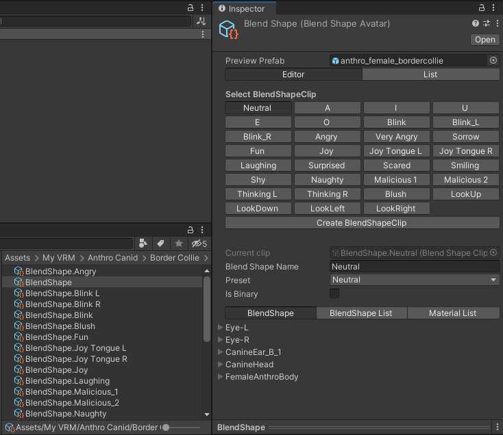
Blend Shapes: contains all of the model's Blendshapes Clips, groups of blend shapes configured together to form expressions. These clips are saved as individual files and combined into the ‘BlendShape’ file. You can configure the clips through each file individually or through ‘BlendShape’, which is more convenient, and this allows you to create new clips by clicking on ‘Create BlendShapeClip’. More details about this editor later.
Materials: contains all the materials used by the model, these define the colors and textures of our model's surfaces. As an example, note that the eyes have three materials, one 'OuterEye' (external part of the eye, used to simulate the eye's reflection or create a highlight effect) shared by both eyes and two 'InnerEye.'(R/L) (part inside the eye, defines its colors), one for each eye. Although each 'InnerEye' has the same configuration as the other, the intention was to be able to load a different texture for each eye for the effect of eyes with heterochromia or scarred eyes. Feel free to test different values in the settings, I won't go into too much detail on this topic, I suggest you read Materials introduction - Unity Manual and MToon - VRM documentation.

Meshes: contains all the meshes of our model, these define the shapes of the surfaces of our model. Note in the 'CanineNose' object, as an example, both the mesh and the GameObject material(s) are loaded into the 'Skinned Mesh Renderer' component, all GameObjects are composed of components. With the mesh selected in 'Inspector' we can see various details such as the number of vertices and triangles, sub-meshes, blend shapes, etc. In the mesh preview we can switch between ‘Shaded’, ‘UV Checker’, ‘UV Layout’, ‘Vertex Color’, ‘Normals’, ‘Tangent’ and ‘BlendShapes’. This data cannot be edited, but it can serve as information to know if the meshes were imported correctly.


Meta Object: contains a file with all the metadata of our model, you can interpret it as an identity card for the model/character. If you have questions about filling in the data in your own model, read Model Information - VRM documentation.

Textures: contains all the model's textures. In 'Inspector' there are several texture settings, including size limits and compression, which can be useful if you need to export a lighter version of the model, as textures can greatly influence the final size of the model. Some applications may require restrictions on the size (total in MB) of the model or the texture resolution (total in pixels). The advantage is that changes are only applied when the texture is exported, the image file being preserved, allowing other configurations to suit a given application.

Blendshapes, materials, textures and meshes can be loaded by components from folders external to the model. When it is exported in VRM format, all these files will be automatically organized and compressed in new folders, all in a single file. It is not recommended to have all the files related to the model scattered in Assets, ideally these files should be in their respective folders corresponding to each model. With some exceptions, for example, eye color textures can be saved in an external folder, as more than one model can use the same texture, which can avoid multiple copies of them.
Avatar Description
Returning to talking about ‘Avatar Description’, I believe it is an adaptation of Unity’s Avatar settings for FBX models. First we will use an FBX model, I will provide an example model for download, but you can use any one. With the model imported (you can simply drag and drop an FBX model into a folder in Assets), go to ‘Rig’, select and in ‘Animation Type’ choose ‘Humanoid’ and click Apply.

An error message may appear, some bones may have been mapped incorrectly. Click on ‘Configure’.

Your example model may not present any problems, but if it does, it could be easy to resolve in the case of a wrong mapping. In the image below, the problem appears in the red area, on the head. Switch from the ‘Body’ tab to ‘Head’. If your model does not have any errors, go directly to ‘Muscles & Settings’.

Now in head, it is reported that the bone ‘EyeBone-L’ is marked in ‘Left Eye’ and ‘Jaw’.

To solve the problem, simply mark ‘Jaw’ as ‘None’. The avatar diagram should now turn all green, indicating that it is now regular. Click on ‘Done’ (below in Inspector) to save the changes.

With the Avatar consistent, go to ‘Muscles & Settings’. The model must load into a scene in a 'Pose Mode' type. We have two 'Preview' settings, 'Muscle Group Preview', with multiple body part poses, and 'Per-Muscle Preview', with body part poses. located on the body. Below 'Additional Settings', note that these settings are similar to VRM's 'Avatar Description'.
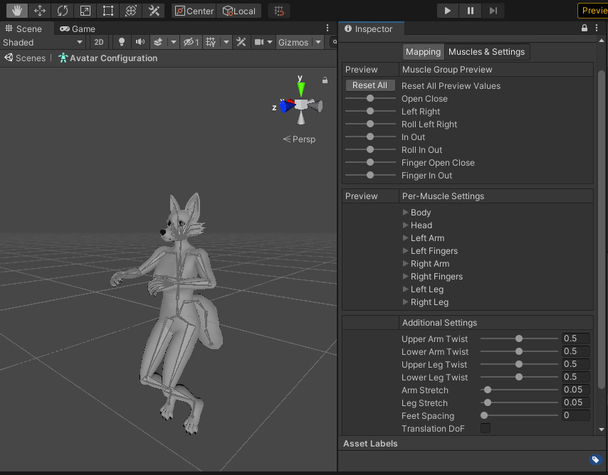
To do a test let's set 'Lower Arm Twist' to 0.0, then in 'Left/Right Arm' > 'ForeArm Twist In-Out' toggle between the maximum and minimum value (by default -90º and 90º, but you can change them if you want). The hand will rotate on its own while the lower arm will remain stationary, which doesn't seem very natural since the parts of the arm rotate together, at different degrees.


Now set ‘Lower Arm Twist’ to 0.5, this time the hand will work in conjunction with lower arm. It is noted that the hand rotation in relation to the lower is more natural compared to the previous test. The results of mesh deformation may vary from one model to another, depending on the rigging/skinning applied, in my sample models the lower arms have a slightly greater influence than the upper arms in the elbow region, in this case I can suggest 'Lower Arm Twist' with a value between 0.2 - 0.3, in the other fields the default values look good, but feel free to test other values.


In other models the influence of weights may be slightly different in some parts of the body, if you want something more optimized I suggest using applications such as AccuRIG or Mixamo, these have advanced auto-rig tools and can give you a better result in mesh deformations in poses. Remembering that my models are modular, perhaps just the body (without the head, tail and other parts) is enough to be used in the aforementioned applications.
Blend Shape Avatar
Returning to the blend shapes settings, this is possibly the most important component or the one you might spend the most time adjusting, especially if the model is aimed at Vtubing, as in this panel we define the character's facial expressions.
Editor: panel with all BlendShape Clips ready to use. When we click on one of them we will notice that the 3D preview will be updated. On some models the 'LookUp', 'LookDown', 'LookLeft' and 'LookRight' clips are not configured, as the eye movements are configured to be driven by bones.

With the 3D preview minimized, we can see more available properties, such as:
Current Clip: informs the file that corresponds to the current clip.
Blend Shape Name: is the name of the expression of the current clip.
Preset: these are clip presets, important for categorizing the standard expressions of VRM models. Each clip must be related to a predefined expression so that they are loaded correctly during run time in some application. It is recommended that each preset is related to just one clip, with the exception of ‘Unknow’. Newly created clips are defined as ‘Unknow’, an undefined category, for non-standard expressions it is recommended to keep them in this preset, otherwise choose the appropriate preset.
Is Binary: when disabled, the clip can vary with values between 0 and 1.0, in practice this allows expressions to have a progressive animation, when enabled, the clip can only assume the maximum and minimum value, this causes the animation of the expression stay instant, more details later.

We also have tabs with more adjustments such as:
BlendShape: lists the objects that are part of the model and their respective blend shapes. Choosing ‘CanineHead’ for example, we can view all the blend shapes of the object, the values correspond to those applied to the ‘Joy Tongue R’ clip.

BlendShape List: lists only pairs of objects and blend shapes applied to the current clip. While in the previous tab we already defined the blend shapes to be used, in this one we only focus on the adjustments of those that were chosen.

Note that each item in a pair has a drop-down list. The objects available in the model are listed in the first, and in the second the blend shapes available in the selected object are listed. It's an interesting feature when we want to make quick adjustments, whether to test or correct one blend shape in place of another.


Material List: creates coloring effects on the selected clip from a model material. The objective is to create an effect that highlights some facial expression, for example, we can make the face all red when ‘Angry’ is active, highlighting the intensity of anger (“She is boiling with anger!”).


In this other example, with 'Scared' active, only the shading of the selected materials changed color, a blue color tone can highlight the intensity of fear ("She frozen with fear!").


List: next to 'Editor', it also brings together the clips ready for use in the model, but in the form of a list instead of a panel, it also has some similar properties. ‘Element’ is equivalent to ‘Current Clip’, but in addition to displaying the file that corresponds to the current clip, it is possible to select another clip file instead. The ‘Blend Shape Name’, ‘Preset’ and ‘Is Binary’ properties are basically the same as those seen in ‘Editor’.

Another differentiator of 'List' is the possibility of reordering the expression clips, for example we can place 'Fun' as the second element, between 'Neutral' and 'A', simply dragging and dropping the clip into the new position. If we go back to ‘Editor’ we will notice that the clip positions have been updated in the panel.


Testing Blend Shapes
With the BlendShapeClips configured, we can test your animations. One way is to select one of the clip files individually, for example we can select the file that corresponds to 'Joy Tongue R', we will notice it has some properties similar to the 'BlendShape' file, but instead of Editor and List we have 'Preview Weight'.

If we move the ‘Preview Weight’ slider we will be able to preview the ‘Joy Tongue R’ animation progressively. You may have noticed that when the slider reaches the intermediate values, more or less between 0.250 and 0.820, the tongue appears to go through the mouth instead of smoothly exiting the mouth and bending at the tip. This strange animation occurs because blend shapes do not support rotations, only vertex translations.
One way to deal with this is to enable the 'Is Binary' option, making the clip only alternate between the minimum and maximum value, without progressive animations generated by intermediate values.
All BlendShape Clips in my sample models have the ‘Is Binary’ option disabled, it is up to you to use this option or not.
Another way to test clip animations is through the 'VRM Blend Shape Proxy' component, as you can see in the image the 'BlendShape' file corresponding to the model is loaded in it, in the 'Blend Shape Avatar' property. This component can only be tested in ‘Play Mode’.

With 'Play Mode' activated, we can view the animations of the model's expressions within the scene, test them all to your heart's content.
VRM Model Components
Now let's talk a little more about the model's components. Every GameObject in Unity is composed of components, more complex models such as 3D characters are usually composed of a parent object (usually with the name of the model), and child objects that represent specific parts of the model such as the body, armature bones, clothing, accessories, etc. Each with its own components. At the beginning of this tutorial we configured components such as spring bones in the 'secondary' object and VRM colliders in some bones. Now let's take a closer look at the components of the parent object.
VRM Meta: loads the Meta file plus its preview into the model. The loaded file can be edited in the component, when trying to change a value the change is made in the file as well and vice versa. You can also try loading other Meta files, this will make the preview change.

VRM Humanoid Description: loads the ‘VrmAvatar’ and ‘AvatarDescription’ files. Other files of the same type can be loaded into the component, but there is no preview of these files and it is not possible to edit them.

Animator: this component is used to assign animations to a GameObject in the current scene. Requires an Animator Controller and avatar file, in this case ‘VRM’. In the context of this project, this component would be used to load and execute animations within Unity only. It would be good for testing or for any other purpose within Unity, like a game or animation, but in our case we only want to export the VRM model, so you can leave it with the default settings. For more details for this component, read Animator component - Unity Manual.

VRM Blend Shape Proxy: loads the model’s ‘BlendShape’ file. As we saw in the previous topic, preview is only available in 'Play Mode'.
VRM First Person: defines the settings for how the model should work in a first-person mode, more common in VR spaces such as Cluster and VirtualCast. First the reference bone, in this case ‘Head’, to define the position of the FirstPerson Camera from the origin of the bone. Below, in ‘First Person Bone Offset’, the relative position that such a camera should be in, in this case something like eye height. In 'Renderers' it will be defined how the model's meshes will be rendered for each type of camera, being ‘ThirdPersonOnly’, ‘FirstPersonOnly’, ‘Booth’ or ‘Auto’.

It is recommended to divide the mesh into head and body during model creation, in case the template model already meets this specification. The head, plus parts close to it must be specified as 'ThirdPersonOnly', while the body and other parts away from the head must be 'Booth'. With the ‘Automatic’ specification the mesh is divided based on the influence weight of the bones, this process is heavier, so prefer the other options.
VRM Look At Head: this component is used for testing, in it we define a target object (Cube) and the bone that corresponds to the head, thus calculating the direction from the model's head to the target. In Debug, the relative rotation, in yaw and pitch, of the head to the target will be visible in ‘Play Mode’. It works in conjunction with ‘VRM Look At ‘Bone Applyer’ or VRM Look At Blend Shape Applyer’, more details later.

VRM Look At Bone Applyer: defines the right and left eyes, selecting the equivalent bones, and eye movement through degree mapping.
Maximum Yaw and Pitch Angle ➤ ‘Curve X Range Degree’
EyeBone rotation angle (right and left) when yaw and pitch angle is at maximum ➤ ‘Curve Y Range Degree’
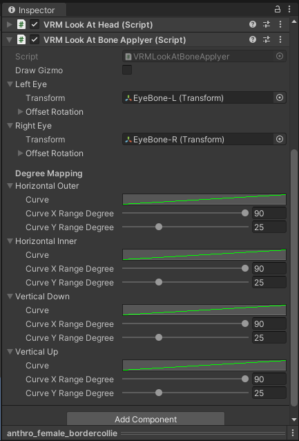
Generally speaking, ‘Curve’ controls the transition of movement through its parameters. In the example below, this is the standard curve when we create a VRM model. In practice, the movement transition is uniform, the speed at which the eyes rotate is the same from beginning to end.

Now in the example below, if we change the linear curve to a constant in all instances of 'Curve', the movement will not have intermediate values, something similar when in Blend Shape Clip 'Is Binary' is enabled.

Other types of curves offer non-uniform transition speeds to movement, such as slower at the beginning and accelerating at the end and vice versa. Curves for animation can be a complex subject, I recommend you read Animation Curves, the ultimate design lever | Unity Blog, for better understanding.
Export
Having completed all configuration and testing, we will now export our model. We can export by selecting the model from its instance in the scene or from its Prefab (I generally prefer the second option, as it is common to use some different configurations in the instance just for testing and leave the final ones in the Prefab), then in the top bar 'VRM0 > Export to VRM 0.x'.
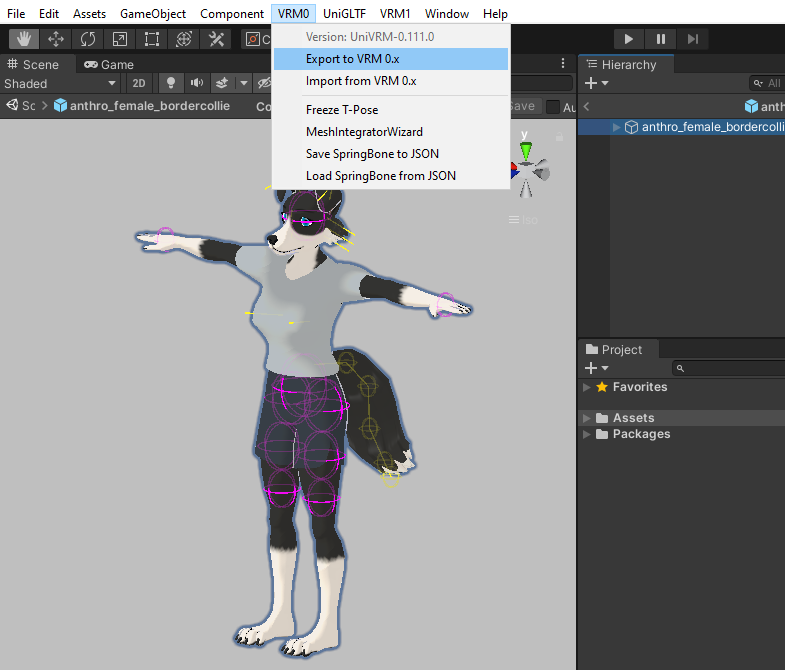
A new window will appear containing the status of our model, in case of any inconsistency an error message will appear. Regarding the T-Pose, our model is already in this pose, if he wasn't we would have to click on 'Make T-Pose'. In the ‘Meta’ tab, check the data again to see if they are all correct.

The ‘Mesh’ tab will contain all active meshes in the model, make sure everything is in order.

In the 'BlendShape' tab, with one of the clips selected, clicking on 'Apply selected BlendShapeClip' will set the corresponding clip values in the model's blend shapes, in 'Clear BlendShape' these values will be reset. In practice, when we apply a Blend Shape Clip and then export it, the current state of the Blend Shapes becomes the initial state. This feature should be used with certain discretion, if the initial state of the face, for example, is an expression similar to neutral, perhaps nothing needs to be done, but otherwise applying the selected clip would be recommended. For blend shapes to be applied during export, the ‘Pose Freeze’ option must be enabled in ‘ExportinSettings’.

Lastly we have ‘ExportinSettings’, as you can see the options are self-explanatory, but if you want more details I recommend you read VRM Export - VRM documentation.

After the final adjustments and without any error messages, we can export our model by clicking on ‘Export’. Now load the newly created VRM file into an application that supports the format. I recommend testing it in offline applications first, such as VseeFace or XR Animator, for the sake of agility. Online platforms like Cluster or VirtualCast can be great for testing the model's entire body, as you can control it like a video game character, but they require registration and can take time to upload.
Conclusion
This was the longest tutorial on the blog so far, even so it was not possible to go over all the possible adjustments of VRM 0.x, I just tried to focus on the essentials. I hope this and other tutorials have helped you create and customize your own avatar, even if you didn't use any of my templates or samples. So that's it for today, see you next time.
Extras
Mecanim humanoids | Unity Blog
What is VTubing and why should brands take notice? | Twitch Ads
Animation Curves, the ultimate design lever | Unity Blog
VRoid Studio Characters and Animation in Unity – Extra Ordinary, the Series
[Tutorial] Springbones: How to add physics to bones [VRM]
Why Animation Curves In Unity Are So Useful
References
Introduction to components - Unity Manual
Editing a Prefab in Prefab Mode - Unity Manual
Materials introduction - Unity Manual
Texture Import Settings - Unity Manual
Skinned Mesh Renderer component - Unity Manual
Humanoid Avatars - Unity Manual
Avatar Mapping tab - Unity Manual
Animator component - Unity Manual
Humanoid Overview - VRM documentation
BlendShape Setting - VRM documentation
BlendShape Setup (v0.45) - VRM documentation
Model Information - VRM documentation
VRM-1.0 Changes - VRM documentation
VRM Export - VRM documentation